Diesel Generators
Manufacturing and Assembly
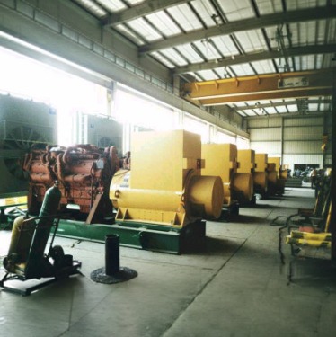
The manufacturing process starts with receiving the design drawings and materials, including the major equipment (engine and alternator). The manufacturing process differs from one manufacturer to another.
While some manufacturers do everything or most of the work in their own factory, others may outsource some or most of the work to more specialized manufacturers who can do it more economically and/or faster. This can include, for example, steel fabrication work for skid bases, fuel tanks, and weather enclosures. Some manufacturers even outsource the control panels and switchgear, and they monitor their quality and do the assembling and testing.
Design
After sizing the diesel generator and configuring all the required auxiliary systems and controls, here comes the next step: How to realize them. What are the different equipment and components that together make the genset, and how are they put together as one system to give the required genset its pre-defined specifications? This is known as the design process.
Some manufacturers design some or all of the genset supporting systems, such as the skid bases, control panels, circuit breaker panels, exhaust system, fuel tanks, weather enclosures, etc., for which these manufacturers should have an engineering design office and produce shop floor drawings and bills of materials. They should have quality control as an after-sales service system.
Design includes electrical control schematic drawings, wiring diagrams, control panels and switchgear general arrangement drawings, components layout drawings, single line diagrams, wires and cables schedule, PLC ladder logic diagrams, controllers setup files, skid base production drawings, genset general arrangement drawing, radiator and pipes layouts, P&ID, power house layout drawing, genset enclosure drawing, genset trailer drawing, and many other detailed drawings which will be used by the manufacturer or his subcontractors for manufacturing and/or installation purposes.
NEC offers one of the best courses on diesel generators worldwide.
Sizing
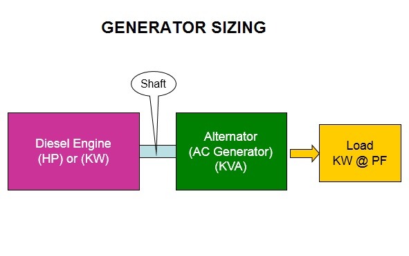
Part of the configuration process of a genset is to answer the questions: What is the size of this genset in terms of kW rating, and what is its reactive capability to withstand the transient loads? The sizing process always starts by sizing the site load and defining the total running loads in kW and starting loads in kVA, and then applying the other site load criteria, such as maximum allowable voltage dip, load factor, and future expansion, to calculate the size of the generator(s).While some manufacturers do everything or most of the work in their own factory, others may outsource some or most of the work to more specialized manufacturers who can do it more economically and/or faster. This can include, for example, steel fabrication work for skid bases, fuel tanks, and weather enclosures. Some manufacturers even outsource the control panels and switchgear, and they monitor their quality and do the assembling and testing.
It should be emphasized here that the power factor is controlled by the load, and it affects the generator by pulling more current as the power factor drops. Loads that have high starting kVAs simply have low starting power factors. When sizing gensets, it is advisable to always limit the starting kVA of the load by using lower-voltage starting methods like star/delta or transformer tap, or, if this is not possible, use sequencing. This is to switch the big starting kVA loads in sequence at 15- to 30-second intervals and not together. NECSize 2008 software can calculate the site load kWs and starting kVAs.
Configuration
When selecting diesel generators, the first questions are what the size of the load is that it is going to supply and what the amounts of both running loads (kW) and starting loads (kVAR) are. What type of loads are going to be supplied? Are there, for example, UPS loads or heavy motor loads? Is the load a steady load or an intermittent switching on-and-off load? This is known as sizing of diesel generators for site loads. The second question is whether the generator is going to run as standby for the mains, or is it going to run as a prime power source.
The third question is how long this investment is going to last. In other words, are we going to select a heavy-duty genset to last more than 5 years, or is it going to be for a few years? Where is the genset going to be installed, and under which environmental conditions? Are there any noise restrictions? Is there any space limitation? What voltage and frequency are this generator going to generate?
All these considerations affect the final decision of which diesel engine prime mover is going to be, which alternator is going to be driven, what the kW rating of this genset is and how it will be installed, what control system is going to be installed, level of protections, cooling system, acoustics, etc. This is known as diesel generator configuration for site loads.
Diesel Engine
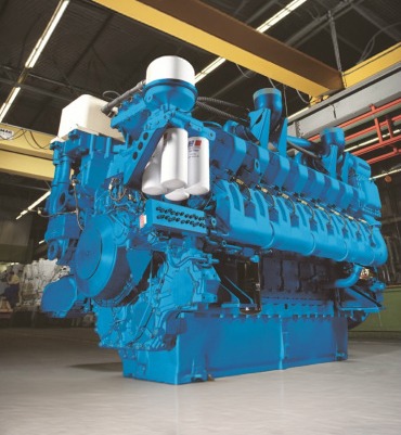
The diesel engine is the most important part of the genset. It is the prime mover that drives the generator (alternator) to produce electricity. All diesel engines are similar to each other in concept, but they differ in many aspects, such as the number of cylinders, whether the cylinders are a line- or V-type, how the fuel is delivered to the cylinders, the governing system, the cooling system, the air charging system, the air intake system, the rotational speed, and, recently, the engine tier for COx and NOx emissions. All these details affect the decision of which engine to use and what performance is expected.
Engines are rated in kW or HP. Their performance is measured by their fuel consumption in liters or gallons per kWh produced, thermal efficiency, noise level, lube oil consumption, and exhaust gas emissions.
AC Generator (Alternator)
The AC generator or alternator is the second major part of the genset. Nowadays, most, if not all, of the alternators are brushless type with a rotating excitation system. The alternator is selected during the configuration process. It should be matched mechanically to the diesel engine. Electrically, the alternator should be selected to provide the required kW at the specified voltage, frequency, ambient temperature, and altitude, and it should be capable of withstanding the transient loads without exceeding the maximum allowable voltage dips.
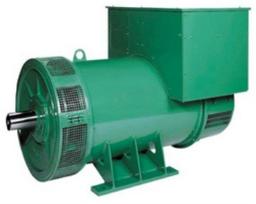
Normally, the automatic voltage regulator (AVR) is supplied as part of the alternator to ensure compatibility. The brushless alternators use a rotating exciter generator to generate the excitation (magnetization) current and voltage required by the main rotor to be excited (magnetized). The AVR controls the amount of excitation given to the rotor based on sensing the generator output voltage. Alternators’ speed should match the diesel engine speed. The lower the speed, the higher the number of rotor poles. This is to maintain a fixed 50 Hz or 60 Hz regardless of the rotation speed.
NEC offers an excellent course on AC generators and excitation systems.
Speed Governing
The two main parameters we must control in the diesel generator sets are speed and voltage. Controlling the speed is controlling the diesel engine prime mover via controlling the fuel. On the other hand, controlling the voltage is controlling the AC generator (alternator) via controlling the excitation of the rotor (magnetization of the rotor). Speed governing, or sometimes we call it speed control, is like any other feedback control system. It consists of a sensing part that measures the running speed of the diesel engine (magnetic pickups).
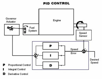
Then, the speed controller compares the actual running speed from the magnetic pickup with the set reference speed and produces an error. This error is then amplified and converted to an output signal to raise or lower the speed via the governor actuator. This is an electronic type. The most famous control is known as PID (Proportional, Integral, and Derivative). Governors can also be a mechanical hydraulic type.
Excitation (Magnetization) Control
As mentioned elsewhere, the excitation is simply magnetizing the rotor to produce a magnetic field. During the rotation of the rotor, the field flux lines intersect with the stator windings, and electromotive force (EMF) will be generated accordingly. Most of the alternators used nowadays are brushless type, where the DC current required to magnetize the rotor is produced by the exciter generator and then rectified using rotating rectifiers. To control the amount of excitation, we need to control the exciter generator.
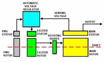
The voltage regulator is used to sense the output voltage of the alternator and then compares it with the setting to produce the error. This error is amplified and modulated to control the field of the exciter. In some applications where the generator is to run in parallel with the mains, the generator reactive power in this case must be controlled so that the generator will not be pulled into an overload situation. PF control is used.
Engine Auxiliary Systems and Instrumentation
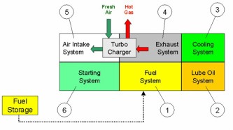
Each genset has auxiliary systems to support its functions. Most, if not all, of these systems are attached to the diesel engine. When the diesel engine burns diesel, it fuels its cooling system, fuel system, lubrication system, air intake system, and exhaust system. Each one of these systems can vary in the design specs even for the same engine; this depends on the application and configuration of the genset. Each of these systems has instrumentation to measure and indicate the operating parameters.
Safeties and Protection
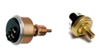
The genset consists of a mechanical part represented by the diesel engine and an electrical part represented by the AC generator (alternator). Each of these two major equipment must be properly protected against abnormal operating parameters. There are, of course, mechanical parameters and electrical parameters. For example, the oil pressure and water temperature are two of the mechanical parameters, while the AC current and voltage are two of the electrical parameters, which we must protect the genset against abnormal values.
Control System
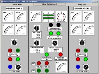
Each genset must have a control system; the control system consists of sensors and actuators connected to a control panel. The control panel normally has a controller, which handles the start and stop of the genset and protects the genset against abnormal operating parameters. The control panel can have a lot of optional controls, protection, and metering devices as per the design to suit the applications and configuration of the genset to meet the customer’s specs.
Switchgear and Power Distribution
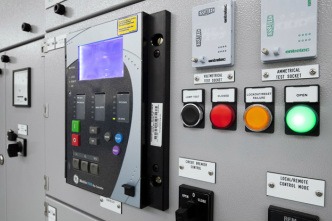
The switchgear is the electrical part of the genset that connects and disconnects the genset’s output electrical power to the load. The switchgear is usually a circuit breaker or a contactor.
Testing Diesel Generators
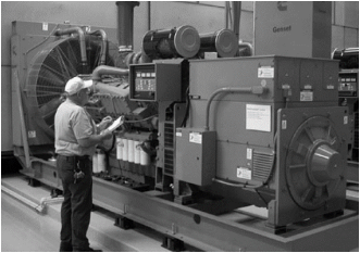
Each manufactured diesel generator set is normally tested at the factory according to the application and configuration of the genset and following design criteria. The purpose of the factory test is to validate the genset design to meet the specified criteria. This includes a functional test, a load test, and a safety and protection test.
Troubleshooting Diesel Generators
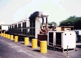
When diesel generator sets operate, whether in standby mode or as prime power, they are expected to encounter some mechanical or electrical problems, which could cause them to either shut down or have their performance degrade. Genset problems vary from simple electrical wiring faults to major engine problems. Troubleshooting the problems in the gensets is simply answering the question: What caused this alarm, or what caused this shutdown, or what caused this erratic behavior?
Troubleshooting is a process starting with collecting the information, then defining the problem. After defining the problem, list all the possible causes of the problem and finally select the solution or solutions that eliminate the problem or problems, taking into consideration the economics and reliability.
Vibration on Diesel Generators
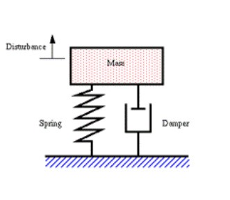
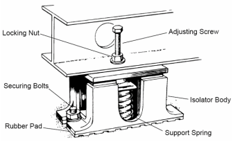
Diesel generator sets can suffer from excessive vibration, which could cause failures and unwanted noise. Vibration can be linear or nonlinear. Sources of linear vibration can come from diesel engine internal combustion forces, misalignment, unbalanced mounting, and structural resonance. Nonlinear vibration can be caused by shaft torsional forces. To control vibration, we need to define its parameters. Then, we need to measure them and know the relationship between them. Then, we control them.
The main vibration parameters are displacement, velocity, acceleration, and frequency. These four (4) parameters are related to each other mathematically. Another parameter, which is necessary for analyzing the vibration and establishing its source, is the vibration order.
Paralleling and Load Sharing Diesel Generators
Based on the results of the load sizing, we may need to have more than one genset to operate in parallel to supply the load. When gensets operate in parallel, they encounter problems not seen when they operate as a standalone. Some of these problems are how to maintain the frequency of the system, how to share the site load, how to eliminate the reactive cross-current, how to control the start and stop of these gensets when the site load increases or decreases, which genset will be the duty genset and which ones will be the non-duty, and so on.The main vibration parameters are displacement, velocity, acceleration, and frequency. These four (4) parameters are related to each other mathematically. Another parameter, which is necessary for analyzing the vibration and establishing its source, is the vibration order.
Exhaust pipes need to be extended to outside the engine room. This also has to be taken into consideration. Ducts for power cables, control cables, and fuel and coolant pipes could be needed, and many more.
Installation of Diesel Generators
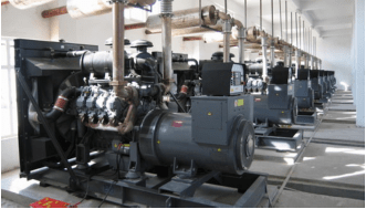
Diesel generators can be as small as 10 kW and can be big to exceed 10,000 kW. When these gensets are to be installed at the site, there are lot of considerations to be taken. Gensets could be as heavy as 50 tons or more. These need concrete foundations to be mounted on. They breathe air for combustion, so fresh filtered air must be brought to them. Gensets need enough space, so engine rooms must be designed to suit them. Gensets require ventilation to reject the heat outside the engine rooms, so inlet and outlet openings are to be integrated within the engine room design.Exhaust pipes need to be extended to outside the engine room. This also has to be taken into consideration. Ducts for power cables, control cables, and fuel and coolant pipes could be needed, and many more.
These challenges require installing a paralleling and load-sharing control system with load demand control. To better understand the system, we need to know, for example, the two modes of paralleling (droop and isochronous) and if the gensets are going to be paralleled with each other or with the mains and so on.
Automatic Transfer Switches
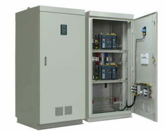
When the diesel generator is used as standby for the mains power, then it requires an automatic transfer switchgear to transfer the load automatically from the mains power to the standby generator when the mains power fails. The ATS can be made or purchased in different styles. The open transition ATS is the most common one, where it transfers the power from the normal source to the emergency source.
The other style is the open transition bypass isolation ATS. This is similar to the first one except the ATS module can be completely isolated from the circuit when it malfunctions, and two bypass switches are used to bypass either the normal power or the emergency power. The third famous style is the closed transition ATS. The difference between open and closed transition is that, in the open transition, the normal side switch opens before the emergency side switch is closed (break before make), while in the closed transition type, the emergency side closes before the normal side opens (make before break).
Other styles are also available.